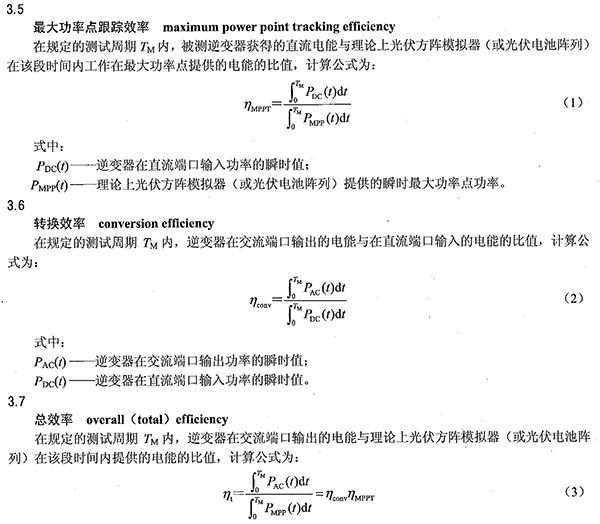
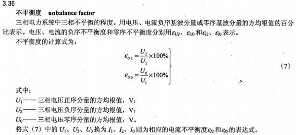
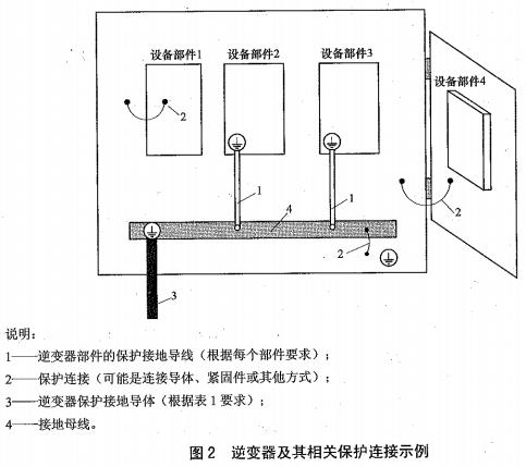
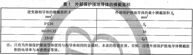
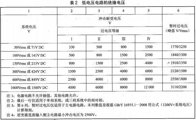
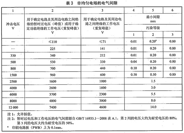
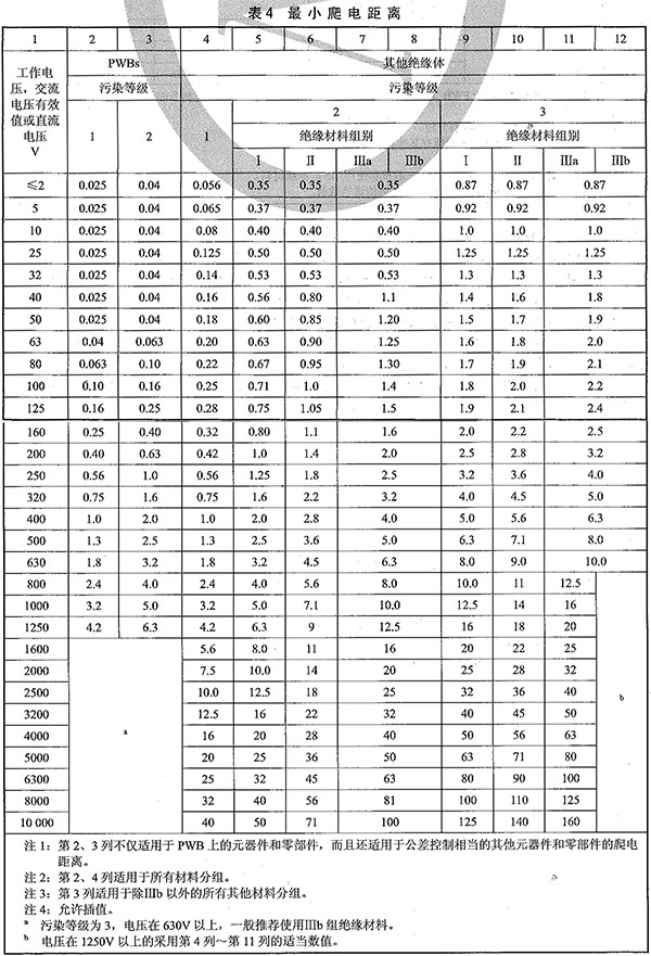
1 Scope This standard specifies the product types, technical requirements, and test methods of inverters used in photovoltaic (Pv) grid-tied systems. This standard is applicable to photovoltaic grid-connected inverters whose voltage is not more than 1500V DC and whose AC output voltage does not exceed 1000V. 2 normative references The following documents are indispensable for the application of this document. For dated references, only dated versions apply to this document. For undated references, the latest version (including all amendments) applies to this document. GB/T 1408.1-2006 Test methods for electrical strength of insulating materials - Part 1: Test at frequency lowers (EEC 60243-1:1998, IDT) GB/T 2423.1-2008 Environmental testing for electric and electronic products Part 2: Test methods Test A: Low temperature (IEC 60068-2-1:2007, IDT) GB/T 2423.2-2008 Environmental testing for electric and electronic products Part 2: Test methods Test B: High temperature (IEC 60068-2-2:2007, IDT) GB/T 2423.3-2006 Environmental testing for electric and electronic products Part 2: Test methods Test Cab: Constant moisture heat test (IEC 60068-2-78:2001, IDT) GB/T 2423.4-2008 Environmental testing for electric and electronic products Part 2: Test methods Test Db: Alternating heat (12h + 12h cycle) U EC 60068-2-30:2005, IDT) GB/T 2423.10-2008 Environmental testing for electric and electronic products Part 2: Test methods Test Fc: Vibration (Sine) QEC 60068-2-6:1995, IDT) GB/T 2828.1-2012 Count sampling inspection procedures Part 1: Lot-by-batch sampling plans searched according to receiving quality (AQL) (ISO 2859-1:1999, IDT) GB/T 3805-2008 Extra Low Voltage (ELV) Limits GB/T 4207 solid insulation material resistance to tracking index and comparison of tracking index (IEC 60112, IDT) GB 4208-2008 Enclosure Protection Level (IP Code) UEC 60529:2001, IDT) GB 4824-2004 Industrial, scientific and medical (ISM) radio frequency equipment electromagnetic disturbance characteristics limit value and measurement method (CISPR 11:2003, IDT) GB/T 5169.10-2006 Fire hazard testing for electric and electronic products - Part 10: Glow/hot wire basic test methods - Glow-wire apparatus and general test method (IEC 60659-2-10:2000, IDT) GB/T 5169.11-2006 Fire hazard testing for electric and electronic products - Part 11: Glow/hot wire basic test methods Glow-wire flammability test method for finished products (IEC 60695-2-11:2000, IDT) GB/T 5169.17-2008 Fire hazard testing for electric and electronic products Part 17: Test flame 500W flame test method (IEC 60695-11-20:2003, IDT) GB/T 5465.2-2008 Graphical symbols for use in electrical equipment - Part 2: Graphical symbols (IEC 60417 DB:2007, IDT) GB/T 12113-2003 Measurement methods for contact current and protective conductor current (IEC 60990:1999, IDT) GB/T 14549-1993 Power Quality Public Power Harmonics GB/T 15543-2008 Three-phase voltage imbalance in power quality GB 16895.3-2004 Electrical installations of buildings - Part 5-54: Selection and installation of electrical equipment - Grounding arrangements, protective conductors and protective conductors (IEC 60364-5-54:2002, IDT) GB/T 16895.10-2010 Low-voltage electrical apparatus - Part 4-44: Protection against voltage disturbances and electromagnetic harassment (IEC 60364-4-44:2007, IDT) GB/T 16935.1-2008 Insulation coordination for equipment in low-voltage systems Part 1: Principles, requirements and tests (IEC 60664-1:2007, IDT) GB 17625.2-2007 Limits for electromagnetic compatibility (IEC 61000-3-3:2005), Limits for voltage variations, voltage fluctuations and flicker in public low-voltage supply systems for equipment with a rated current of less than or equal to 16 A per phase and unconditional access IDT) GB/T 17626.2-2006 Electromagnetic compatibility Testing and measurement techniques Electrostatic discharge immunity test (IEC 61000-4-2: 2001, IDT) GB/T 17626.3-2006 Electromagnetic compatibility test and measurement technology Radio frequency electromagnetic field radiation immunity test (IEC 61000-4-3:2002, IDT) GB/T 17626.4-2008 Electromagnetic compatibility Testing and measurement techniques Electrical fast transient burst immunity test (IEC 61000-4-4:2004, IDT) GB/T 17626.5-2008 Electromagnetic compatibility Testing and measurement techniques Surge (impact) immunity test (IEC 61000-4-5:2005, IDT) GB/T 17626.6-2008 Electromagnetic compatibility Testing and measurement techniques Conducted disturbance immunity of radio frequency fields (IEC 61000-4-6:2006, IDT) GB/T 17626.8-2006 Electromagnetic Compatibility Testing and Measurement Technology Power Frequency Magnetic Field Immunity Test (IEC 61000-4-8:2001, IDT) GB/T 17626.11-2008 Electromagnetic compatibility Testing and measurement techniques Voltage dips, short interruptions and voltage variations immunity test (IEC 61000-4-11:2004, IDT) GB/T 17626.12-1998 Electromagnetic compatibility test and measurement techniques Oscillatory wave immunity test (IEC 61000-4-12:1995, IDT) GB/T 17626.14-2005 Electromagnetic compatibility test and measurement techniques Voltage fluctuation immunity test (IEC 61000-4-14:2002, IDT) GB/T 17627.2-1998 High-voltage test techniques for low-voltage electrical equipment Part 2: Measurement systems and test equipment (IEC 1180-2:1994, EQV) GB/T 18479-2001 Overview and guidance for ground-use photovoltaic (Pv) power generation systems (IEC 61277:1995, IDT) GB/T 19939-2005 Photovoltaic system grid connection technical requirements GB/T 25919.1-2010 Modbus test specification - Part 1: Specification for Modbus serial link conformance testing GB/T 25919.2-2010 Modbus test specification - Part 2: Specification for Modbus serial link interoperability test IEC 60028 International Standard of Resistance for Copper IEC 60417 Graphical Symbols for Use on Equipment IEC 60664-4:2005 Insulation arrangements for low-voltage electrical equipment - Part 4: Lisulation Coordination Ordination for Equipment within Low-voltage Systems Part 4: Considerations of High-frequency Voltage Stress IEC 60695-2-20:2004 Fire hazard testing - Part 2-20: Basic test methods based on glow/hot wire - Test methods and guidelines for hot wire ignition test equipment (Fire Hazard Testing Part 2-20: Glowing/ Hot Wire Based Test Methods Hot-wire Coil Ignitability Apparatus, Test Method and Guidance General Requirements for Residual Current Operated Protective Devices (IEC 60755) IEC 60950-1:2005 Information technology equipment safety - Part 1: General requirements (Informstion Technology Equipment - Safety Part 1: General Requirements) IEC 60990 Method of Measurement of Touch Current and Protective Conductor Current IEC 61032 uses Protection of Persons and Equipment by Enclosures-probes for Verification (Protection of Persons and Equipment by Enclosures-probes for Verification) IEC 61180-1:1992 High-voltage test techniques for low-voltage equipment - Part 1: Definitions, tests and procedural requirements (High-voltage Test Techniques for Low-voltage Equipment Part 1: Definitions, Test and Procedure Requirements) ISO 178-2010 Plastics - Determination of flexural properties (Plastics - Detennination of Flexural Properties) ISO 179-1-2010 Plastics - Determination of pendulum impact properties - Part 1: Non-instrumented Impact Test (Plastics Determination of Charpy Impact Properties Part 1: Non-instrumented Impact Test) ISO 180-2010 Plastics - Determination of Izod Impact Strength (Plastics--Determination of Lzod Impact Strength) ISO 3864-1 Graphic Symbols Safety Colours and Safety Markings Part 1: Design Principles for Safety Signs and Safety Markings in the Workplace and Public Domains (Graphical Symbols--Safety Colors and Safety Signs Part 1: Design Principles for Safety Signs and Safety Markings) ISO 4892-1 Plastics - Laboratory light source exposure methods - Part 1: General principles (Plastics - Exposure to Laboratory Light Source Part 1: General Guidance) ISO 4892-2 Plastics - Laboratory light source exposure methods - Part 2: X-ray arc lamps (Plastics - Exposure to Laboratory Light Sources Part 2: Xenon-arc Lamps) ISO 4892-4 Plastics - Laboratory light source exposure methods - Part 4: Open-air carbon arc lamps (Plastics - Exposure to Laboratory Light Sources Part 4: Open-flame Carbon-arc Lamps) ISO 527-1-2012 Plastics - Determination of tensile properties - Part 1: General principles (Plastics - Oetermination of Tensile Properties Part 1: General Principles) ISO 7000 Equipment Graphical Symbols and Lists (Graphical Symbols for Use on Equipment - Index and Synopsis) ISO 8256-2004 Plastics - Determination of impact strength (Plastics - determination of Tensile-impact Strength) EN 50530-2010 Integrated Efficiency of Photovoltaic Inverters for Grid-connected PV Inverters 3 Terms and Definitions 3.1 Photovoltaic grid-connected inverter photovoltaic grid-connected inverter The equipment that converts the DC power from the PV array into AC power and feeds it into the grid. Note 1: The inverters mentioned in this standard refer to photovoltaic grid-connected inverters. Note 2: The technical requirements and test methods specified in this standard are not applicable to inverters in AC MODULE. 3.2 Photovoltaic array simulator A power source that simulates the static and dynamic current and voltage characteristics of a photovoltaic array. 3.3 Inverter AC output terminal inverter AC output terminal The connection point of the external output power on the AC side of the inverter. 3.4 Maximum power point tracking; MPPT The output voltage and current changes caused by changes in the surface temperature of the photovoltaic array and the change in the solar illuminance are tracked and controlled so that the array is kept at the maximum output state to obtain the maximum power output automatic adjustment behavior. 3.8 Islanding islanding When the power grid loses voltage, the photovoltaic system maintains the state of power supply to a portion of the missing piezoelectric network. 3.9 Anti-islanding A function that prohibits the islanding effect. Note: When the unplanned islanding effect occurs, due to the unknown status of the system power supply, the following adverse effects will be caused: it may endanger the life safety of maintenance personnel and users of the power grid lines; interfere with the normal closing of the grid; the grid cannot control the voltage and frequency in isolated islands. , thereby damaging the distribution equipment and user equipment. 3.10 Grid simulated power AC simulated power The test power supply used to simulate the public power grid has adjustable output voltage and frequency. 3.13 Clearance Clearance The shortest spatial distance between two conductive parts. 3.14 Closed electrical operating area Room or area where the electrical equipment is used. There is a clear warning sign in this area. Only personnel with relevant skills or specially trained personnel are allowed to enter, and the door or the barrier must be opened with a key or tool before entering. 3.15 Creepage distance The shortest distance between two conductive parts along the surface of the insulating material. 3.16 Enclosure Encloses internal components to prevent external influences, flame spread, and dangerous parts of the equipment. 3.17 Fire enclosure Encloses internal components and minimizes the components of the internal flame and the spread of combustion. 3.18 Electrical protective enclosure Enclose the internal components and limit the parts of the equipment that reach areas that are at risk of electrical shock, energy, or burns. 3.19 Pollution degree With a digital rating, the micro-environment within or around the equipment is expected to be contaminated. 3.20 Live parts Conductors or conductive parts that are energized during normal use, including neutral conductors, but do not routinely include protective neutral (PEN) conductors. Note: This part does not necessarily include a shock hazard. 3.21 Sample test A random number of samples are taken from a batch of products for testing. 3.22 Type test light pe test A test performed on one or more devices manufactured to a design to demonstrate that the device design meets certain specifications. 3.23 Working voltage The maximum effective value of the AC voltage or DC voltage that may be generated across any particular insulation of the equipment at the rated voltage. Note: Instantaneous phenomena are not considered. Both open circuit and normal operation must be considered. 3.24 Basic insulation basic insulation Insulation for basic protection against electric shock under non-fault conditions. Note: Does not apply to insulation intended for functional purposes. 3.25 Double insulated double insulation Insulation consisting of both basic insulation and supplementary insulation. 3.26 Reinforced insulation reinforced insulation A single insulation system added to a live part provides a level of protection against electric shock equivalent to double insulation under specified conditions. Note: A single insulation system does not mean that the insulation must be a homogeneous substance. It can be composed of multiple insulation layers, but it cannot be tested by dividing it into basic insulation or additional insulation layer by layer. 3.27 Additional insulation supplementary insulauon In addition to the basic insulation used for fault protection, separate insulation is provided. 3.28 Transient overvoltage transient overvoltage Oscillating or non-oscillating, usually high damping durations are only a few milliseconds or less overvoltage. 3.29 Protection class I protecuve class I Electrical shock is prevented by the basic insulation and the protective earthing of the accessible conductive parts, so that the contactable conductor cannot be charged when the basic insulation fails. 3.30 Protection class II protective class II Not only the basic insulation to prevent electric shock, but also provides additional safety precautions such as double insulation or reinforced insulation. This protection does not rely on protective grounding nor on installation conditions. 3.31 Protection class III protective class III Devices that prevent electric shock by limiting voltage levels and do not generate dangerous voltages themselves. Note: For Class III protection equipment, although there is no requirement to prevent electric shock, it applies to all other requirements of this standard. 3.32 Basic protection Electrical shock protection without fault conditions. Note: For low-voltage devices, systems and equipment, the basic protection generally corresponds to the direct contact protection specified in GB 16895.21-2011. 3.33 Uniform field homogenous field The voltage gradient between the electrodes is a substantially constant electric field (a uniform electric field). For example, the electric field of each ball between two balls is greater than the distance between them. Note: The uniform electric field condition is called Case B. 3.34 Inhomogeneous electric field The voltage gradient between the electrodes is a substantially non-constant electric field (a non-uniform electric field). Note: With respect to voltage withstand capability, the non-uniform electric field condition of the tip versus the planar electrode structure is the worst case and is called Case A. It can be represented by a 30 m dot electrode and a 1 m x 1 m planar electrode. 3.35 Temporary overvoltage Power frequency overvoltage that lasts for a relatively long time (relative to transient overvoltage). 4 inverter type 4.1 Classifying the number of output phases according to the AC side According to the output side of the AC side can be divided into: - Single-phase inverters; - Three-phase inverter. 4.2 According to the installation environment According to the installation environment can be divided into: - Indoor type I (with temperature adjustment device); - Indoor Type II (without temperature adjustment device); - Outdoor type. 4.3 Classified by electrical isolation According to electrical isolation can be divided into: - Isolated; - Non-isolated. 4.4 Classification by Application According to the application can be divided into: - Household type; - Industrial type (such as power plants, factories, etc.). 4.5 Classified by usage scale According to the scale of use can be divided into: 电站 Power station type grid-connected inverters (not less than 1MW power station); - Non-power grid-connected inverters. 4.6 Other classifications Other types not stated above that are stated by the manufacturer. 5 Inverter identification and data 5.1 Identification 5.1.1 General requirements a) In addition to the identification of internal components, all markings shall be visible from the outside after installation; the markings for the entire product shall not be placed on parts that can be removed by the operator without tools. b) Logos may use graphic symbols provided that they comply with the relevant requirements of A.1 or GB/T 5465.2-2008. The documentation provided by the inverter should explain the graphical symbols used. c) The inverter should at least permanently mark the following: 1) The name or trademark of the manufacturer or supplier; 2) Used to identify the model or name of the inverter; 3) The serial number, code or other identification used to identify the origin, batch or date. Lots or dates are accurate to within 3 months, and the method of date identification does not show duplicate figures for 30 years. The compliance of this article is verified by inspection. 5.1.2 Inverter Rated Parameters Unless otherwise specified in this standard, the following applicable parameters shall be marked on the inverter: - input voltage range, voltage type, and maximum input current; - output voltage level, voltage type, frequency, maximum continuous operating current, and rated power of the AC output; - IP protection level. The compliance of this article is verified by inspection. 5.1.3 Inverter Components and Interfaces 5.1.3.1 Fuse identification a) The fuse identification should give its rated current. If the fuse base can be fitted with fuses of different voltage levels, the marking should also give its rated voltage. The marking should be close to the fuse or fuse base, or marked directly on the fuse base. It can also be marked in other positions, but it is necessary to clearly distinguish the fuses to which the marks refer. b) If it is necessary to use fuses with specific fuse characteristics (eg delay time and breaking capacity), the fuse type should be indicated. c) For fuses installed outside the operator contact area, and in the operator contact area but fixedly welded fuses, only a specific reference symbol (eg FU1, FU2, etc.) may be marked and shall be in the service manual. Explain the relevant information. 5.1.3.2 Switchgear The opening and closing position of the switchgear must be clearly marked. If the power supply adopts a push-button switch, the 10th or 16th symbol in Table A.1 can be used to mark the position of “ONâ€, and the 11th or 17th symbol in Table A.1 is used to mark “OFFâ€. position. These symbols need to be used in pairs, ie the 10th and 11th symbols in Table A.1, or the 16th and 17th symbols. 5.1.3.3 Interface Identification a) If safety is necessary, instructions should be given for terminals, connectors, controls, and indicators and their various positions, including coolant filling and cable connections (if applicable). You can refer to the symbols given in Table A.1; if the position is not enough, you can use the ninth symbol in Table A.1. Note: There are multiple pins for signal, control and communication connectors. It is not necessary to label each pin, but only the use of the entire connector. b) On the buttons and brakes of the emergency brake device, the indicator light used to warn the danger or indicate that emergency treatment is required shall be used in red. c) Multi-voltage supply inverters must be marked with the factory-set voltage. The logo allows the use of paper labels or other non-permanent materials. d) The polarity of the connection must be clearly marked on the DC terminal of the inverter: 1) "+" indicates positive electrode, "-" indicates negative electrode; 2) Other graphic symbols that accurately describe the polarity. e) The connection terminals of the protective earth conductor are marked as follows: 1) The 7th symbol in Table A.1; 2) The letter "PE"; 3) Yellow-green two-color wire. 5.1.4 Durability of the logo This clause requires that the markings on the inverter must be clearly identifiable under normal conditions of use and that it should be able to withstand the corrosion of the cleaning agent specified by the manufacturer. The compliance of this article is verified by inspections and durability tests on the exterior of the inverter. Using a cloth impregnated with the designated cleaning agent, quickly wipe the label 15s manually with normal pressure (approx. 10N). If the manufacturer does not specify a cleaning agent, replace it with acetone. After wiping, the logo must remain legible, and the attached label must not be loose or curled. 5.2 Documentation 5.2.1 General requirements a) The documentation should explain the safe operation and installation of the inverter; if necessary, the inverter maintenance instructions and the following contents can also be given: 1) Explain the identification on the inverter, including the symbols used. 2) Position and function of terminals and controllers. 3) All parameters and specifications related to the safe installation and operation of the inverter, including the following environmental parameters, and their meaning and effect: - Environmental classification; - Classification of wet places; ——preset the pollution level of the external environment; - IP protection level; - ambient temperature and relative humidity; - Overvoltage category for each input and output port. 4) Warning that the photovoltaic matrix is ​​illuminated and the DC voltage is input to the inverter. b) Installation instructions, operating instructions, maintenance instructions, etc. Safety-related documentation should be prepared using the universal language of the inverter. c) Documents must be printed and supplied with the inverter. Note: Electronic versions of documents can be provided with printed documents, but they cannot replace printed documents. 5.2.2 Installation Instructions The documentation must include installation instructions, as well as detailed commissioning instructions. For safety reasons, warnings must be given as to the dangers that may occur during installation and commissioning. The information provided by the documentation should include: a) requirements for assembly, positioning and fixing; b) the parameters and connection methods of each power supply, the requirements for wiring, external controllers, wire color codes, disconnection methods, and required over-current protection, and instructions as to where the installation location must not interfere with the disconnection of the power supply; c) parameters and connection methods for each output of the inverter, as well as requirements for wiring, external controllers, wire color codes and required over-current protection; d) ventilation requirements; e) special maintenance requirements such as coolant requirements (where applicable); f) noise level related instructions and instructions; g) Description of protective grounding. 5.2.3 Operation Instructions The operating instructions should include all necessary information to ensure safe operation, including the following applicable content: a) Description of controller settings, adjustment methods, and adjustment effects; b) instructions for connecting accessories and other equipment, and clearly applicable accessories, removable parts and special materials; c) warnings of the danger of burns and measures to reduce the risk required by the operator; d) Indication that the protection measures may be invalid if the inverter is used in a manner not specified by the manufacturer. 5.2.4 Maintenance Instructions a) The maintenance instructions include the following information: 1) Regular maintenance intervals and instructions required to ensure safety (for example, replacement of air filters or regular reinforcement of terminals, etc.); 2) Instructions for the operator contact area (where applicable), including warnings not to enter specific areas of the inverter; 3) The number and description of parts and components make it easy to find parts that can be replaced by the operator; 4) Explain the safe cleaning method (if applicable). b) If the inverter is powered by multiple channels, the manual shall state the sequence in which the switching devices are disconnected. 6 Use, installation and transportation conditions 6.1 Normal use, installation and transportation conditions 6.1.1 Normal Conditions of Use 6.1.1.1 Ambient air temperature - Indoor air temperature range of indoor inverter: indoor type I 0 °C +40 °C; indoor type -20 °C +40 °C. - Outdoor air temperature range of outdoor inverters: a 5 °C ~ +60 °C. 6.1.1.2 Altitude The altitude of the installation site does not exceed 1000m. Note: When the altitude is higher than 1000m, the inverter current capacity will be lower than the specified value as the altitude increases; when the altitude is higher than 2000m, the cooling effect of air and the decrease of dielectric strength need to be considered. Inverters operating under this condition shall be designed or used in accordance with the manufacturer's and user's agreement. For abnormal use of altitude, see 6.2.2.2. 6.1.1.3 Atmospheric conditions 6.1.1.3.1 Humidity ——Relative Humidity Range of Indoor Inverters: Indoor Type I 5%-85% without condensation; Indoor Type II 5%-95% without condensation. - Outdoor inverter relative humidity range: 4% to 100%, with condensation. At a temperature of +40°C, the relative air humidity does not exceed 50%. Allows higher relative humidity at lower temperatures, up to 100% at +25°C. Special measures should be taken for occasional condensation caused by temperature changes. 6.1.1.3.2 Pollution Level a) The pollution level is related to the environmental conditions in which the inverter is used. Note: The micro-environment of the clearance or creepage distance determines the effect on the electrical insulation, not the product's environment to determine its effect. The microscopic environment of the clearance or creepage distance may be better or worse than the product's environment. The micro-environment includes all factors that affect insulation, such as climatic conditions, electromagnetic conditions, and the generation of pollution. b) For the electrical appliances used in the enclosure or the electrical enclosures with its own enclosure, the pollution level may be selected within the enclosure. c) In order to facilitate the determination of electrical clearances and creepage distances, the micro-environment can be divided into four levels of pollution. 1) Pollution Level 1: No pollution or only dry, non-conductive pollution. 2) Pollution Level 2: Normally there is only non-conductive pollution, but it is necessary to take into account the temporary conductive pollution caused by accidental condensation. 3) Pollution level 3: Conductive pollution, or dry non-conductive pollution due to condensation becomes conductive pollution. 4) Pollution Level 4: Persistent conductive pollution, eg due to conductive dust or rain and snow. Outdoor inverters and indoor type II inverters are generally suitable for pollution level 3 environments; indoor type I inverters are generally suitable for pollution level 2 environments. However, other levels of contamination may be considered for special applications and microcosmic environments. For inverters intended for use in a pollution level 4 environment, measures must be taken to reduce the micro-environment pollution level to 1, 2, and 3 levels. If the inverter itself is contaminated or wet (for example, conductive contaminants from the motor carbon brushes, or condensation from the cooling system), the pollution level in specific areas of the inverter will increase. 6.1.1.4 Impact Vibration Inverters may be subject to shock and vibration during production, transportation, installation, operation and maintenance. Therefore, reasonable precautions must be taken to avoid damage. Inverters used in normal operation, transportation, etc. can be verified using the method of 8.6.4. Impact and vibration conditions that inverters can withstand when used in abnormal operating, transportation, etc. environments are under consideration. 6.1.2 Transportation and Storage If the conditions of transport and storage of the inverter are different from those specified in 6.1, the manufacturer and the user shall reach a special agreement. For inverters of more than 50kg, the marking of the center of gravity of the inverter must be given on the package for ease of transportation and handling. 6.1.3 Installation The inverter should be installed according to the manufacturer's instructions. 6.2 Abnormal Usage, Installation and Transportation Conditions 6.2.1 General If the actual operation and use conditions of the inverter are different from the conditions specified in 6.1, the user shall propose the difference between the conditions used in the condition and the standard conditions, and negotiate with the manufacturer for adaptability under the conditions. For transportation and installation conditions, see 6.1.2, 6.1.3. 6.2.2 Abnormal conditions 6.2.2.1 Ambient air temperature The ambient air temperature is expected to be below -25°C or above +60°C. 6.2.2.2 Elevation a) When the altitude of the inverter installation site is higher than 1000m, the current capacity will be lower than the specified value because the air is thin and the heat dissipation capacity is affected. Assuming that the temperature of the cooling medium remains constant, Figure 1 shows the curve of current capacity as a function of altitude. b) The temperature decreases with increasing altitude. According to the climate characteristics of China, the ambient temperature drops by 0.5°C for every 100m above sea level. For current capacity correction of inverters used in high altitude areas, account shall be taken of both the unfavorable factors of decreasing current capacity with increasing altitude and the favorable factors for the decrease of ambient temperature. c) When the altitude of the inverter installation site is higher than 2000m, it is also necessary to consider the decrease of electrical dielectric strength. 6.2.2.3 Atmospheric conditions The relative humidity in the place where the inverter is installed is greater than the prescribed value of 6.1.3, or the atmosphere contains excessive amounts of dust, acidic substances, and corrosive gases. If the inverter is installed offshore. 6.2.2.4 Installation Conditions The inverter is mounted on a mobile device, or on an electrical support member that is in a tilted position for a long or short period of time (for example, on a ship), or the inverter is subjected to abnormal shock or vibration during use. 6.2.2.5 Other conditions Other abnormal conditions are under consideration. 7 Structure and Performance Requirements 7.1 Structural Materials 7.1.1 Temperature rise a) Under the action of electricity, the inverter is affected and affected by thermal stress, and its structural safety may be reduced, and at the same time, it may have unfavorable effects on safety. Unusual temperatures can cause dangerous areas where protection is required: 1) Accessible parts that exceed the safe temperature. 2) Parts, parts, insulation, and plastic materials that exceed a specified temperature. The inverter is within its expected service life, and when it is used normally, the electrical, mechanical and other properties may be reduced if this specific temperature is exceeded. 3) Structures and mounting surfaces that exceed a certain temperature. Exceeding this temperature may shorten the expected life of the inverter and its components. b) Under normal circumstances, if the relevant components of the inverter or its surface temperature does not change more than 1K/h, the inverter is considered to have reached a thermal stability state. At full power conditions, the temperature rise test lasts for a maximum of 7 hours (simulation of daylight conditions). But except if longer tests will make it more dangerous. c) The effect of temperature on the material and test methods are given in 8.4.2.2. Note: The temperature rise under normal use conditions may differ from the test value, depending on the installation conditions and the dimensions of the connecting conductors. 7.1.2 UV exposure The external plastic parts of outdoor inverters are exposed to ultraviolet radiation, and the degree of danger protection should not be less than that specified in Appendix B. Polymer materials need to be evaluated for their resistance to UV radiation and should comply with Appendix B. If the component degradation does not affect the protection it provides, the requirements of this clause may be ignored. 7.1.3 Shell Protection Level The inverter shall have protective measures for the enclosure to prevent the human body from approaching the dangerous parts in the enclosure and prevent the entry of solid foreign matter and water, so as to avoid adverse effects on the inverter. The inverter can adopt different shell protection measures according to different occasions. The outdoor inverters must meet the IP54 requirements at minimum, and the indoor inverters must meet the IP20 requirements. 7.2 Electric shock protection requirements 7.2.1 Overview Electric shock protection is a protective measure taken against the foreseeable misuse of the inverter during its intended life, installation, operation and maintenance. 7.2.2 Direct Contact Protection Requirements 7.2.2.1 General requirements a) Prevent people from coming into direct contact with live parts that cause harm to people. Measures to prevent direct contact should be achieved by one or more of the measures specified in 7.2.2.2 or 7.2.2.3. b) Open parts and devices do not require direct contact protection. However, the operating instructions must explicitly require the final product to provide the necessary protective measures after installation. c) Inverters scheduled to be installed in closed electrical operating areas do not require direct contact protection. If maintenance personnel need to energize the inverter during installation or maintenance, protective measures must comply with the requirements of 7.2.2.2.3. 7.2.2.2 Shell and Barrier Protection 7.2.2.2.1 General requirements Provide a protective shell and security barrier, and its components should not be removed without the use of tools. Polymer materials that meet these requirements should meet the requirements of 7.1.1 and 7.4 at the same time. When the inverter is used outdoors, the outer shell polymer material must meet the requirements of 7.1.2 when it is exposed to sunlight. 7.2.2.2.2 Preventing Contact Requirements a) After passing through the enclosure and safety protection, the distance between people and live parts must meet the following requirements: 1) The voltage of live parts is less than or equal to the specified safety voltage - it can be touched; 2) The voltage of the live parts is greater than the specified safety voltage - not accessible, and there must be sufficient clearance between the live parts and the parts, ie, the basic insulation clearance requirements determined by the repeated peak operating voltage of the circuit under consideration. Note: The provisions of safety voltage limits in accordance with the provisions of GB/T 3805-2008. b) If the inverter is protected by enclosures or barriers, the minimum IPXXB (also IP2X) degree of enclosure protection as specified in GB 4208-2008 shall be used to carry out the inspection in accordance with 8.2.3.1 to prevent the dangerous liveness from being touched. section. 7.2.2.2.3 Maintenance personnel contact area If the enclosure needs to be opened during installation or maintenance, and the inverter needs to be powered, it may be inadvertently touched in the course of maintenance. The live parts of the voltage should provide protection against contact. Protection requirements are inspected in accordance with 8.2.3.1. 7.2.2.3 Insulation protection of live parts Insulation should be determined according to the inverter's surge voltage, temporary overvoltage or operating voltage, and select the most severe condition according to the requirements of 7.2.4. The insulation protection should not be removed without the use of tools. 7.2.3 Indirect Contact Protection Requirements 7.2.3.1 General requirements a) In the event of an insulation failure, in order to prevent contact with an electric current that presents a risk of electric shock, indirect contact protection is required. Indirect contact There are generally three ways to protect: Protection class I - basic insulation and protective grounding; Protection class II - double insulation or reinforced insulation; Protection class III - voltage limits. b) If the indirect contact protection depends on the installation method, the installation instructions must clearly indicate the relevant hazard and specify the installation method. c) Circuits that are insulated by indirect protection shall be protected according to 7.2.4. d) Circuits with a voltage less than the specified safety voltage [see 7.2.2.2.2 a)) have no risk of electric shock. 7.2.3.2 Ground Protection Connection Requirements 7.2.3.2.1 General requirements a) When the live parts and contactable conductive parts are connected incorrectly, the corresponding protective connection should be able to withstand the maximum thermal stress and dynamic stress caused thereby. The protective connection shall also remain valid in the event of a failure of accessible conductive parts, unless the protective device of the preceding stage cuts off the power supply of that part. b) The inverter provides a protective connection and ensures that the conductors are accessible to the electrical connection to the external ground protection. Figure 2 shows an example of an inverter and its associated protection connections. 7.2.3.2.2 Connection method a) The electrical grounding protection connection of the inverter should choose the following method: 1) through a direct metal connection; 2) Connect other components that will not be removed when using the inverter; 3) Through a dedicated protection connection; 4) Connect with other metal components of the inverter. b) Two parts of direct metal connection. When there is coating or paint at the contact, the coating or paint shall be scraped to ensure the direct contact between metal and metal. c) When the electrical inverter is mounted on a cover, door or cover, for example, special connection conductors, fasteners, hinges may be used to ensure the continuity of the protection connection, and the impedance thereof needs to meet the requirements of 7.2.3.2.3. d) Metallic hoses or rigid tubes and metal sleeves generally cannot be used as protective conductors, unless these devices or materials have been shown to be suitable for protective attachment. 7.2.3.2.3 Protection connection requirements The protection connection should meet the following requirements: a) For inverters whose rated current of the overcurrent protection device is less than or equal to 16A, the value of the protection connection shall not exceed 0.1 Ω. b) For inverters with an overcurrent protection device rated greater than 16A in the circuit, the voltage drop across the protective connection shall not exceed 2.5V. Protective connection measurement and inspection see 8.2.3.2. 7.2.3.3 External Protection Ground Connection Requirements 7.2.3.3.1 General requirements 逆å˜å™¨é€šç”µåŽå¤–部ä¿æŠ¤æŽ¥åœ°å¯¼ä½“应始终ä¿æŒè¿žæŽ¥ã€‚除éžå½“地的é…线设计规则有ä¸åŒè¦æ±‚,å¦åˆ™å¤–部ä¿æŠ¤æŽ¥åœ°å¯¼ä½“的横截é¢ç§¯éœ€ç¬¦åˆè¡¨1çš„è¦æ±‚ï¼Œæˆ–è€…æ ¹æ®GB 16895.3-2004进行计算。 7.2.3.3.2è¿žæŽ¥æ–¹å¼ a)æ¯ä¸ªé¢„定需通过ä¿æŠ¤è¿žæŽ¥ä¸Žåœ°ç›¸è¿žçš„逆å˜å™¨ï¼Œéƒ½éœ€åœ¨é 近相应ä¿æŠ¤è¿žæŽ¥å¯¼ä½“的地方æ供一个连接端å。这个连接端å需进行防è…蚀处ç†ï¼Œå¹¶ä¸”符åˆ7.2.3.3.1的规定。 b)外部ä¿æŠ¤æŽ¥åœ°å¯¼ä½“的连接方å¼ä¸èƒ½ç”¨ä½œå…¶ä»–连接的机械组件。 c)æ¯ä¸ªå¤–部ä¿æŠ¤æŽ¥åœ°å¯¼ä½“应使用å•ç‹¬çš„连接方å¼ã€‚ d)连接点的电æµå®¹é‡ä¸èƒ½å› 机械ã€åŒ–å¦æˆ–电化å¦å½±å“而é™ä½Žã€‚若外壳和导体采用é“或é“åˆé‡‘,需特别注æ„电解液è…蚀的问题。 e)接地回路ä¸ä¸åº”安装熔æ–器ç‰çŸè·¯ä¿æŠ¤å¼€å…³è£…置。 7.2.3.3.3æŽ¥è§¦ç”µæµ ä¸ºäº†åœ¨ä¿æŠ¤æŽ¥åœ°å¯¼ä½“å—æŸæˆ–被æ–开的情况下ä¿æŒå®‰å…¨ï¼Œå¯¹äºŽæ’头连接的逆å˜å™¨ï¼Œä½¿ç”¨GB/T 12113- 2003试验图4所规定的试验电路,测得的接触电æµä¸åº”超过3.5mAAC或10mA DC。 注1:GB/T 12113-2003试验图4å‚è§é™„录C。 注2:注æ„外部试验æºå’Œåœ°ä¹‹é—´çš„电容对接触电æµæµ‹é‡çš„å½±å“。 对于所有其他逆å˜å™¨æˆ–æ ¹æ®ä»¥ä¸Šè¦æ±‚测é‡æŽ¥è§¦ç”µæµï¼ˆè§8.2.3.3),å¯é‡‡ç”¨ä»¥ä¸‹ä¸€ä¸ªæˆ–多个ä¿æŠ¤æŽªæ–½ï¼š a)固定连接: 1)ä¿æŠ¤æŽ¥åœ°å¯¼ä½“的横截é¢ç§¯è‡³å°‘为10mm2(铜)或16mm2(é“); 2)在ä¿æŠ¤æŽ¥åœ°å¯¼ä½“ä¸æ–情况下自动æ–开电æºï¼› 3)有二次ä¿æŠ¤æŽ¥åœ°è¦æ±‚的须在安装说明书ä¸æ³¨æ˜Žï¼Œä¸”采用的二次ä¿æŠ¤æŽ¥åœ°å¯¼ä½“的截é¢ç§¯é¡»ä¸Žä¸€æ¬¡ä¿æŠ¤æŽ¥åœ°å¯¼ä½“的截é¢ç§¯ç›¸åŒï¼Œå¹¶æä¾›å¦å¤–的接地端。 b)用IEC 60309-1:2005规定的工业连接器进行连接,而且多导体电缆ä¸ä¿æŠ¤æŽ¥åœ°å¯¼ä½“的最å°æ¨ªæˆªé¢ç§¯ä¸º2.5mm2。 7.2.4ç»ç¼˜é…åˆ 7.2.4.1一般è¦æ±‚ æ ¹æ®é€†å˜å™¨çš„使用åŠå…¶å‘¨å›´çš„环境æ¥ç¡®å®šå…¶ç”µæ°”特性。 åªæœ‰åŸºäºŽåœ¨å…¶æœŸæœ›å¯¿å‘½ä¸æ‰€æ‰¿å—的应力(如电压)时æ‰èƒ½å®žçŽ°çš„ç»ç¼˜é…åˆã€‚ 7.2.4.2污染ç‰çº§ 逆å˜å™¨çš„ç»ç¼˜åœ¨ä½¿ç”¨æœŸé—´ä¼šå—到污染的影å“,尤其是通过电气间隙的空气ç»ç¼˜å’Œçˆ¬ç”µè·ç¦»çš„固体ç»ç¼˜ã€‚逆å˜å™¨éœ€æ»¡è¶³çš„最低污染ç‰çº§åº”æ ¹æ®6.1.1.3.2çš„è¦æ±‚确定。 7.2.4.3过电压 7.2.4.3.1概述 过电压类别按GB/T 16895.10-2010ä¸443æ¡æ¬¾åˆ¤åˆ«ï¼š ——类别Ⅳ的设备是使用在é…电装置电æºä¸çš„设备。 注:æ¤ç±»è®¾å¤‡åŒ…å«å¦‚测é‡ä»ªå’Œå‰çº§è¿‡ç”µæµä¿æŠ¤è®¾å¤‡ã€‚ ——类别Ⅲ的设备是固定å¼é…电装置ä¸çš„设备,以åŠè®¾å¤‡çš„å¯é 性和适用性必须符åˆç‰¹æ®Šè¦æ±‚者。 注:æ¤ç±»è®¾å¤‡åŒ…å«å¦‚安装在固定å¼é…电装置ä¸çš„开关电器和永久连接至固定å¼é…电装置的工业用设备。 ——类别Ⅱ的设备是由固定å¼é…电装置供电的耗能设备。 注:æ¤ç±»è®¾å¤‡åŒ…å«å¦‚器具ã€å¯ç§»åŠ¨å¼å·¥å…·åŠå…¶ä»–家用和类似用途负载。如果对æ¤ç±»è®¾å¤‡çš„å¯é 性和适用性有特殊è¦æ±‚时,则采用过电压类别Ⅲ。 â€”â€”ç±»åˆ«â… çš„è®¾å¤‡æ˜¯è¿žæŽ¥è‡³å…·æœ‰é™åˆ¶çž¬æ—¶è¿‡ç”µåŽ‹è‡³ç›¸å½“低水平措施的电路的设备。 注:除éžç”µè·¯è®¾è®¡æ—¶è€ƒè™‘了暂时过电压,å¦åˆ™è¿‡ç”µåŽ‹ç±»åˆ«ä¸ºâ… 的设备ä¸èƒ½ç›´æŽ¥è¿žæŽ¥äºŽç”µç½‘ä¸ã€‚ 7.2.4.3.2 PV电路过电压 一般情况下,Pv电路的过电压ç‰çº§å®šä¸ºâ…¡çº§ï¼Œå†²å‡»è€åŽ‹åˆ†çº§ä¾æ®Pv系统电压è§è¡¨20 PV电路冲击è€åŽ‹ä¸å°äºŽ2500V。 7.2.4.3.3电æºç”µè·¯è¿‡ç”µåŽ‹ 一般情况下,电æºç”µè·¯è¿‡ç”µåŽ‹è€ƒè™‘ç‰çº§ä¸ºâ…¢çº§ï¼Œå†²å‡»è€åŽ‹è§è¡¨2。 注:电æºç”µè·¯è¿‡ç”µåŽ‹ç‰çº§ä¸ä¸€å®šä¸ºm级,æŸäº›å®‰è£…环境需è¦è€ƒè™‘W级过电压。逆å˜å™¨æ供的安装信æ¯éœ€è¯´æ˜Žè¿‡ç”µåŽ‹ç‰çº§ã€‚ 7.2.4.4ç»ç¼˜ä½ç½® 7.2.4.4.1电路与其周边电路之间 电路åŠå…¶å‘¨è¾¹ç”µè·¯ä¹‹é—´çš„基本ç»ç¼˜ã€é™„åŠ ç»ç¼˜å’ŒåŠ 强ç»ç¼˜çš„è®¾è®¡éœ€è€ƒè™‘ä»¥ä¸‹å› ç´ ï¼š ——冲击电压; ——暂时过电压; ——电路的é¢å®šå·¥ä½œç”µåŽ‹ã€‚ 7.2.4.4.2直接连接电网的电路 直接连接到电网的电路åŠå…¶å‘¨è¾¹ç”µè·¯ä¹‹é—´çš„电气间隙和固体ç»ç¼˜åº”æ ¹æ®å†²å‡»ç”µåŽ‹ã€æš‚时过电压或工作电压进行设计,选择三者ä¸è¦æ±‚最严酷的。 7.2.4.4.3主电路以外的电路 a)两个电路之间的ç»ç¼˜è®¾è®¡åº”æ ¹æ®å¯¹ç»ç¼˜æœ‰è¾ƒé«˜è¦æ±‚的电路æ¥ç¡®å®šã€‚对于电气间隙和固体ç»ç¼˜ï¼Œç”±æœ‰è¾ƒé«˜å†²å‡»ç”µåŽ‹è¦æ±‚的电路决定。对于爬电è·ç¦»ï¼Œç”±æœ‰è¾ƒé«˜çš„工作电压有效值的电路决定。 b)主电路以外的电路åŠå…¶å‘¨è¾¹ç”µè·¯ä¹‹é—´çš„电气间隙和固体ç»ç¼˜ï¼Œéœ€æ ¹æ®å†²å‡»ç”µåŽ‹å’Œé‡å¤å³°å€¼ç”µåŽ‹è¿›è¡Œè®¾è®¡ï¼Œå¹¶è€ƒè™‘以下è¦æ±‚: ——系统电压:对于Pv电路,å–最大é¢å®šPv开路电压;对于其他电路,å–工作电压。 ——冲击电压è§è¡¨2ï¼Œæ ¹æ®ä¸Šè¿°ç³»ç»Ÿç”µåŽ‹å’Œ7.2.4.3规定的过电压ç‰çº§æŸ¥è¡¨ç¡®å®šã€‚ â€”â€”ç”µæ°”é—´éš™çš„è®¾è®¡æ ¹æ®å·¥ä½œç”µåŽ‹æˆ–冲击电压æ¥ç¡®å®šï¼Œå–二者ä¸è¦æ±‚较严酷的。 7.2.4.5ç»ç¼˜ææ–™ ç»ç¼˜æ料应符åˆGB/T 16935.1-2008ä¸4.8çš„è¦æ±‚。 å°†ç»ç¼˜æ料按相比电痕化指数CTi值划分为4组,CTiå€¼æ˜¯æ ¹æ®GB/T 4207使用溶液A测得的。具体的分组如下: ——ç»ç¼˜ææ–™ç»„åˆ«â… CTI≥600; ——ç»ç¼˜æ料组别Ⅱ CTI≥400; ——ç»ç¼˜æ料组别Ⅲa CTI≥175; ——ç»ç¼˜æ料组别Ⅲb CTI≥100。 ç»ç¼˜ææ–™å¯ç”¨è€ç”µç—•åŒ–指数(PTI)æ¥è¡¨æ˜Žè€ç”µç—•åŒ–æ€§èƒ½ã€‚æ ¹æ®GB/T 4207规定的方法使用溶液A验è¯PTI值。 按GB/T 4207ä¸ç›¸æ¯”电痕化指数(CTi)试验比较å„ç§ç»ç¼˜æ料在试验æ¡ä»¶ä¸‹çš„性能,å¯è¿›è¡Œå®šæ€§æ¯”较,åŒæ—¶å°±ç»ç¼˜æ料具有形æˆæ¼ç”µç—•è¿¹çš„趋å‘æ¥è¯´ï¼Œç›¸æ¯”电痕化指数试验也å¯è¿›è¡Œå®šé‡æ¯”较。 玻璃ã€é™¶ç“·æˆ–å…¶ä»–æ— æœºç»ç¼˜ææ–™ä¸ä¼šå‘生电痕化,爬电è·ç¦»æ— 需大于其相应的为实现ç»ç¼˜é…åˆè€Œè¦æ±‚的电气间隙。 7.2.4.6电气间隙 7.2.4.6.1概述 电气间隙除考虑7.2.4.2è¦æ±‚外,还需考虑如下影å“å› ç´ ï¼š ——电场æ¡ä»¶ï¼› ——功能ç»ç¼˜ã€åŸºæœ¬ç»ç¼˜ã€é™„件ç»ç¼˜å’ŒåŠ 强ç»ç¼˜çš„冲击è€å—电压è¦æ±‚ï¼› ——海拔。 7.2.4.6.2电场æ¡ä»¶ 7.2.4.6.2.1概述 导电部件(电æžï¼‰çš„形状和布置会影å“电场的å‡åŒ€æ€§ï¼Œè¿›è€Œå½±å“è€å—规定的电压所需è¦çš„电气间隙。 7.2.4.6.2.2éžå‡åŒ€ç”µåœºæ¡ä»¶ 由于ä¸èƒ½æŽ§åˆ¶å½¢çŠ¶ç»“构,å¯èƒ½ä¼šå¯¹ç”µåœºçš„å‡åŒ€æ€§äº§ç”Ÿä¸åˆ©å½±å“ï¼Œå› æ¤é€šè¿‡ç»ç¼˜æ料外壳ç¼éš™çš„电气间隙应ä¸å°äºŽéžå‡åŒ€ç”µåœºæ¡ä»¶è§„定的电气间隙。 表3为éžå‡åŒ€ç”µåœºçš„电气间隙,选用ä¸å°äºŽè¡¨3所列的电气间隙å¯ä¸å¿…考虑导电部件的形状结构,也ä¸å¿…用电压è€å—试验进行验è¯ã€‚ 用在海拔2000m-20000m的逆å˜å™¨ï¼Œç”µæ°”é—´éš™éœ€æ ¹æ®GB/T 16935.1-2008表A.2(å‚è§é™„录D)çš„ä¿®æ£å› å进行修æ£ã€‚ 电气间隙的符åˆæ€§åº”通过测é‡æ¥éªŒè¯ï¼›å¿…è¦æ—¶éœ€è¿›è¡Œ8.2.3.4的冲击è€åŽ‹è¯•éªŒå’Œç»ç¼˜è€åŽ‹è¯•éªŒã€‚ 7.2.4.6.2.3å‡åŒ€ç”µåœºæ¡ä»¶ åªæœ‰å½“导电部件(电æžï¼‰çš„形状结构设计æˆä½¿è¯¥å¤„电场强度基本上为æ’定的电压梯度时æ‰èƒ½è®¤ä¸ºç”µåœºå‡åŒ€ã€‚如果确定电场是å‡åŒ€åˆ†å¸ƒçš„,而且冲击电压大于或ç‰äºŽ6000V(对于直接连接电网的电路)或4000V(电路内部),那么电气间隙å¯ä»¥å‡å°åˆ°GB/T 16935.1-2008表E2ä¸æƒ…况B的电气间隙值。 7.2.4.6.3功能ç»ç¼˜çš„电气间隙的确定 è¦æ±‚è€å—电压是逆å˜å™¨åœ¨é¢å®šæ¡ä»¶ä¸‹è·¨ç”µæ°”间隙两端预期å‘生的最大冲击电压或暂时过电压(è§è¡¨2),对应的电气间隙è§è¡¨3。 7.2.4.6.4基本ç»ç¼˜ã€é™„åŠ ç»ç¼˜å’ŒåŠ 强ç»ç¼˜çš„电气间隙的确定 基本ç»ç¼˜å’Œé™„åŠ ç»ç¼˜çš„电气间隙按表3的第2.3列确定。 åŠ å¼ºç»ç¼˜çš„电气间隙按表3的第1列确定。对应的电压值应以下一个更高的脉冲电压,或者1.6å€çš„暂时过电压,或1.6å€çš„工作电压为最高电压值。 7.2.4.6.5æµ·æ‹” 表3ä¸è§„定的éžå‡åŒ€ç”µåœºçš„电气间隙对从海平é¢è‡³æµ·æ‹”2000må‡æœ‰æ•ˆï¼Œé™„录D规定的海拔修æ£ç³»æ•°é€‚åˆäºŽæµ·æ‹”高于2000m的电气间隙。 7.2.4.7爬电è·ç¦» 7.2.4.7.1概述 a)爬电è·ç¦»è¦è¶³å¤Ÿå¤§ä»¥é˜²æ¢å›ºä½“ç»ç¼˜è¡¨é¢é•¿æœŸé€€åŒ–。对于功能ç»ç¼˜ã€åŸºæœ¬ç»ç¼˜å’Œé™„åŠ ç»ç¼˜ï¼Œç›´æŽ¥é‡‡ç”¨è¡¨4ä¸çš„æ•°å€¼ã€‚å¯¹äºŽåŠ å¼ºç»ç¼˜è¡¨4ä¸æ•°å€¼è¦åŠ å€ã€‚ b)当表4规定的爬电è·ç¦»å°äºŽ7.2.4.6规定的或由冲击试验确定的电气间隙时,爬电è·ç¦»è¦å¢žåŠ 到与电气间隙相åŒã€‚ c)表4ä¸çš„值适用于大多数情况,爬电è·ç¦»åº”从表4ä¸é€‰å–,且必须考虑以下影å“å› ç´ ï¼š ——电压; ——污染; ——爬电è·ç¦»çš„æ–¹å‘å’Œä½ç½®ï¼› ——ç»ç¼˜è¡¨é¢çš„形状; ——ç»ç¼˜æ料。 爬电è·ç¦»é€šè¿‡æµ‹é‡æ£€éªŒï¼Œæµ‹è¯•æ–¹æ³•è§8.2.3.4.7。 7.2.4.7.2电压 确定爬电è·ç¦»æ˜¯ä»¥ä½œç”¨åœ¨è·¨æŽ¥çˆ¬ç”µè·ç¦»ä¸¤ç«¯çš„长期电压有效值为基础的。电压è§è¡¨4ä¸çš„第1列,å…许æ’值。 7.2.4.7.3污染 表4ä¸æ•°æ®å·²è€ƒè™‘了微观环境污染ç‰çº§å¯¹ç¡®å®šçˆ¬ç”µè·ç¦»çš„å½±å“。 注:逆å˜å™¨ä¸å¯èƒ½å˜åœ¨ä¸åŒçš„微观环境æ¡ä»¶ã€‚ 7.2.4.7.4爬电è·ç¦»çš„æ–¹å‘å’Œä½ç½® 如有必è¦ï¼Œåˆ¶é€ 商应指明逆å˜å™¨æˆ–元件预期使用的方å‘å’Œä½ç½®ï¼Œä»¥ä¾¿åœ¨è®¾è®¡æ—¶è€ƒè™‘污染的积累对爬电è·ç¦»çš„ä¸åˆ©å½±å“。 注:必须考虑长期å˜æ”¾çš„情况。 7.2.4.7.5功能ç»ç¼˜çš„爬电è·ç¦»çš„确定 功能ç»ç¼˜çš„爬电è·ç¦»åº”按表4规定的对应于跨接爬电è·ç¦»ä¸¤ç«¯çš„实际工作电压确定。 当用实际工作电压æ¥ç¡®å®šçˆ¬ç”µè·ç¦»æ—¶ï¼Œå…许用æ’入值确定ä¸é—´ç”µåŽ‹çš„爬电è·ç¦»ã€‚应使用线性æ’入法求æ’入值,并将所得值的ä½æ•°ä¿ç•™åˆ°ä¸Žè¡¨4ä¸æ•°å€¼ç›¸åŒçš„有效ä½æ•°ã€‚ 7.2.4.7.6基本ç»ç¼˜ã€é™„åŠ ç»ç¼˜å’ŒåŠ 强ç»ç¼˜çš„爬电è·ç¦»çš„确定 基本ç»ç¼˜å’Œé™„åŠ ç»ç¼˜çš„爬电è·ç¦»åº”从表4ä¸ç¡®å®šã€‚å…许使用æ’入值确定ä¸é—´ç”µåŽ‹çš„爬电è·ç¦»ã€‚应使用线性æ’入法求æ’入值,并将所得值的ä½æ•°è°ƒæ•´åˆ°ä¸Žè¡¨ä¸æ•°å€¼ç›¸åŒçš„ä½æ•°ã€‚ å› åŒé‡ç»ç¼˜æ˜¯ç”±åŸºæœ¬ç»ç¼˜å’Œé™„åŠ ç»ç¼˜ç»„æˆçš„,故åŒé‡ç»ç¼˜çš„爬电è·ç¦»æ˜¯åŸºæœ¬ç»ç¼˜çˆ¬ç”µè·ç¦»å’Œé™„åŠ ç»ç¼˜çˆ¬ç”µè·ç¦»çš„总和。 åŠ å¼ºç»ç¼˜çš„爬电è·ç¦»åº”为表4ä¸åŸºæœ¬ç»ç¼˜æ‰€ç¡®å®šå€¼çš„2å€ã€‚ 7.2.4.8固体ç»ç¼˜ 7.2.4.8.1概述 由于固体ç»ç¼˜çš„电气强度远远大于空气的电气强度,故在设计低压ç»ç¼˜ç³»ç»Ÿæ—¶å¯èƒ½ä¸å¤Ÿé‡è§†ã€‚一方é¢ï¼Œé€šè¿‡å›ºä½“ç»ç¼˜æ料的ç»ç¼˜è·ç¦»é€šå¸¸è¿œå°äºŽç”µæ°”间隙而产生高的电应力,å¦ä¸€æ–¹é¢ï¼Œå®žé™…上很少采用高电气强度的æ料。在ç»ç¼˜ç³»ç»Ÿä¸ç”µæžä¸Žç»ç¼˜ä¹‹é—´å’Œä¸åŒçš„ç»ç¼˜å±‚之间å‡å¯èƒ½äº§ç”Ÿé—´éš™ï¼Œæˆ–ç»ç¼˜æ料本身有气隙。在这些间隙或气隙ä¸ï¼Œå³ä½¿ç”µåŽ‹è¿œå°äºŽå‡»ç©¿æ°´å¹³ï¼Œä»å¯èƒ½å‘生局部放电,这就会影å“固体ç»ç¼˜çš„使用寿命。 许多ä¸åˆ©å½±å“会在固体ç»ç¼˜çš„使用寿命期内积累,由æ¤å½¢æˆå¤æ‚的过程,且最终导致ç»ç¼˜è€åŒ–。电应力和其他应力(例如çƒã€çŽ¯å¢ƒï¼‰çš„å åŠ ä¼šé€ æˆç»ç¼˜è€åŒ–。 å¯ç”¨çŸæœŸè¯•éªŒç»“åˆé€‚当的æ¡ä»¶å¤„ç†ï¼ˆè§8.6)æ¥æ¨¡æ‹Ÿå›ºä½“ç»ç¼˜çš„长期性能。 固体ç»ç¼˜çš„厚度与其失效机ç†ä¹‹é—´å˜åœ¨ä¸€å®šçš„è”系。固体ç»ç¼˜çš„厚度å‡å°‘,电场强度éšä¹‹å¢žåŠ ,失效的风险也éšä¹‹ä¸Šå‡ã€‚由于ä¸å¯èƒ½è®¡ç®—出固体ç»ç¼˜çš„æ‰€éœ€åŽšåº¦ï¼Œå› æ¤åªèƒ½é€šè¿‡è¯•éªŒæ¥éªŒè¯å…¶æ€§èƒ½ã€‚ 7.2.4.8.2应力 7.2.4.8.2.1电压频率 电压频率会æžå¤§åœ°å½±å“电气强度,介质å‘çƒå’Œçƒä¸ç¨³å®šæ€§çš„概率基本与频率æˆæ£æ¯”。按照GB/T 1408.1-2006,在工频下测é‡æ—¶ï¼ŒåŽšåº¦ä¸º3mm的固体ç»ç¼˜çš„击穿电场强度为10kV/mm-40kV/mm。æé«˜æ–½åŠ çš„ç”µåŽ‹é¢‘çŽ‡ä¼šé™ä½Žå¤§å¤šæ•°ç»ç¼˜æ料的电气强度。 注:高于30kHz的频率对电气强度的影å“è§IEC 60664-4:2005. 7.2.4.8.2.2å‘çƒ å‘çƒå¯ä»¥é€ æˆï¼š â€”â€”ç”±äºŽå†…åº”åŠ›çš„æ¶ˆé™¤é€ æˆæœºæ¢°ä¸Šçš„å˜å½¢ï¼› ——在高于环境温度(例如温度高于60℃)的较低温å‡ä¸‹çƒå¡‘性æ料软化; ——由于塑化剂æŸå¤±é€ æˆæŸäº›æ料脆裂; ——如果超过æ料的玻璃化转å˜æ¸©åº¦ï¼ŒæŸäº›äº¤è”æ料会软化; ——增大介电æŸè€—导致çƒä¸ç¨³å®šæ€§å’ŒæŸå。 7.2.4.8.2.3机械冲击 如果ææ–™ä¸å…·æœ‰è¶³å¤Ÿçš„æŠ—æ’žå‡»å¼ºåº¦ï¼Œæœºæ¢°å†²å‡»ä¼šé€ æˆç»ç¼˜æŸåã€‚å› æ¤ï¼Œåœ¨è§„定è¿è¾“ã€å‚¨å˜ã€å®‰è£…和使用的环境æ¡ä»¶æ—¶è¦è€ƒè™‘æ¤æƒ…况。 7.2.4.8.2.4局部放电(PD) 如果跨在ç»ç¼˜ä»¶ä¸Šçš„工作电压é‡å¤å³°å€¼å¤§äºŽ700V且ç»ç¼˜ä»¶ä¸Šçš„电压应力大于1kV/mm,è¦è¿›è¡Œå±€éƒ¨æ”¾ç”µè¯•éªŒã€‚ 局部放电特性å—外施电压频率的影å“。在增高频率的æ¡ä»¶ä¸‹è¿›è¡ŒåŠ 速寿命试验,å¯è¯å®žå¤±æ•ˆæ—¶é—´åŸºæœ¬ä¸Žå¤–施电压的频率æˆå比。但实际ç»éªŒä»…包括5kHzåŠä»¥ä¸‹çš„é¢‘çŽ‡ï¼Œå› ä¸ºåœ¨è¾ƒé«˜çš„é¢‘çŽ‡ä¸‹ä¹Ÿä¼šå˜åœ¨ä¸€äº›å…¶ä»–的失效机ç†ï¼Œå¦‚电介质å‘çƒã€‚ 注:高于30kHz的频率对局部放电的影å“è§IEC 60664-4:2005。 7.2.4.8.2.5湿度 水蒸气å¯èƒ½ä¼šå½±å“ç»ç¼˜ç”µé˜»å’Œæ”¾ç”µç†„çç”µåŽ‹ï¼ŒåŠ å‰§è¡¨é¢æ±¡æŸ“,è…蚀外形。对于æŸäº›æ料,高湿度会大大é™ä½Žå…¶ç”µæ°”强度。在æŸäº›æƒ…况下,低湿度也å¯èƒ½æ˜¯ä¸åˆ©çš„,例如会增大é™ç”µç”µè·çš„滞留,会é™ä½ŽæŸäº›æ料(如èšé…žèƒºï¼‰çš„机械强度。 7.2.4.8.2.6其他应力 æŸäº›åº”力的影å“ä¸å¤ªé‡è¦æˆ–å½±å“较å°ï¼Œä½†åœ¨ç‰¹å®šæƒ…况下,还是应引起注æ„,如: ——紫外线è¾å°„和电离è¾å°„ï¼› ——暴露于溶剂或活性化å¦å‰‚ä¸é€ æˆçš„应力裂纹或应力æ–裂; ——塑化剂è¿ç§»ä½œç”¨ï¼› ——霉èŒç‰èŒç±»ã€ç»†èŒçš„作用; ——机械塑性å˜å½¢ç‰ã€‚ 7.2.4.8.3è¦æ±‚ 7.2.4.8.3.1概述 基本ç»ç¼˜ã€é™„åŠ ç»ç¼˜å’ŒåŠ 强ç»ç¼˜çš„固定ç»ç¼˜åº”能æŒä¹…地承å—电场强度和机械应力,并能在逆å˜å™¨çš„预期寿命期内承å—å¯èƒ½äº§ç”Ÿçš„çƒå½±å“和环境影å“。 7.2.4.8.3.2è€å—电压应力 基本ç»ç¼˜å’Œé™„åŠ ç»ç¼˜åº”能承å—以下试验电压: aï¼‰æ ¹æ®8.2.3.4.2确定冲击电压; bï¼‰æ ¹æ®8.2.3.4.3确定适当的交æµæˆ–ç›´æµç”µåŽ‹ã€‚ åŒé‡æˆ–åŠ å¼ºç»ç¼˜åº”能承å—以下试验电压: aï¼‰æ ¹æ®8.2.3.4.2确定冲击电压; bï¼‰æ ¹æ®8.2.3.4.3确定适当的交æµæˆ–ç›´æµç”µåŽ‹ï¼› c)如果跨在ç»ç¼˜ä»¶ä¸Šçš„工作电压é‡å¤å³°å€¼å¤§äºŽ700V且ç»ç¼˜ä»¶ä¸Šçš„电压应力大于1kV/mm,è¦è¿›è¡Œ8.2.3.4.6的局部放电试验。 如果逆å˜å™¨çš„试验ä¸èƒ½è€ƒæ ¸å…ƒå™¨ä»¶æˆ–组件内部的åŒé‡ç»ç¼˜æˆ–åŠ å¼ºç»ç¼˜ï¼Œè¿˜åº”在元器件或组件上进行。 如果元器件符åˆç›¸å…³æ ‡å‡†å¹¶ä¸”å…¶åˆ¶é€ å•†æœ‰å¯é çš„è´¨é‡æŽ§åˆ¶ä½“ç³»ï¼Œé‚£ä¹ˆå…ƒå™¨ä»¶çš„æŠ½æ ·è¯•éªŒå¯ä»¥ä¸åšã€‚ 7.2.4.8.3.3承å—机械应力 在预期使用ä¸å¯èƒ½å‡ºçŽ°çš„机械振动或冲击ä¸åº”æŸå固体ç»ç¼˜ã€‚ 7.2.4.8.3.4承å—æ¹¿åº¦å½±å“ é€†å˜å™¨åœ¨è§„定湿度æ¡ä»¶ä¸‹åº”ä¿æŒç»ç¼˜é…åˆã€‚ 7.2.4.8.3.5承å—其他应力 逆å˜å™¨å¯èƒ½æ‰¿å—其他应力,这些应力å¯èƒ½ä¼šå¯¹å›ºä½“ç»ç¼˜äº§ç”Ÿçš„ä¸åˆ©å½±å“æ£åœ¨è€ƒè™‘ä¸ã€‚ 7.2.5电能å±é™©é˜²æŠ¤ 7.2.5.1å±é™©èƒ½é‡ç‰çº§çš„确定 出现下列两ç§æƒ…况之一,则认为å˜åœ¨å±é™©èƒ½é‡ç‰çº§ï¼š a)电压大于ç‰äºŽ2V,且60s之åŽå®¹é‡è¶…过240VA。 通过以下试验æ¥æ£€éªŒå…¶ç¬¦åˆæ€§ï¼šé€†å˜å™¨å·¥ä½œåœ¨æ£å¸¸å·¥ä½œæ¡ä»¶ä¸‹ï¼Œè°ƒæ•´è¿žæŽ¥å…ƒå™¨ä»¶çš„å¯å˜ç”µé˜»è´Ÿè½½ï¼Œä½¿è¾“出达到240VA,然åŽç»´æŒ60s(适用时,å¯è¿›ä¸€æ¥è°ƒæ•´ï¼‰ã€‚如果æ¤æ—¶ç”µåŽ‹å¤§äºŽç‰äºŽ2V,则输出功率处于 å±é™©èƒ½é‡æ°´å¹³ï¼Œé™¤éžè¿‡ç”µæµä¿æŠ¤è£…置在试验期间动作,或出于æŸç§åŽŸå› 功率ä¸èƒ½åœ¨240VA下维æŒ60s。 b)电容器电压U大于ç‰äºŽ2V,按以下公å¼è®¡ç®—的电能E超过20J。 7.2.5.2æ“作人员接触区 逆å˜å™¨çš„设计应ä¿è¯æ“作人员在接触区内å¯è§¦åŠçš„电路ä¸äº§ç”Ÿå±é™©èƒ½é‡ã€‚ 如果两个或更多裸露零部件(其ä¸ä¸€ä¸ªå¯èƒ½æŽ¥åœ°ï¼‰ä¹‹é—´å˜åœ¨å±é™©èƒ½é‡ï¼Œå®ƒä»¬è¢«é‡‘属物体桥接时å¯èƒ½ä¼šå¼•èµ·ä¼¤å®³ã€‚零部件之间被桥接的å¯èƒ½æ€§é€šè¿‡å›¾E.1规定的试验指æ¥ç¡®å®šã€‚能够被试验指桥接的零部件之间,一定ä¸èƒ½å˜åœ¨å±é™©èƒ½é‡ã€‚ 除了é™åˆ¶èƒ½é‡å¤–,还å¯æä¾›å±éšœã€æŠ¤æ 和类似的防æ¢æ— æ„接触的措施。 7.2.5.3维修人员接触区 ä½äºŽç»´ä¿®æˆ–安装时å¯èƒ½è¢«ç§»åŠ¨æˆ–移除的æ“作é¢æ¿ä¸çš„电容器,逆å˜å™¨æ–电之åŽç”µå®¹å™¨å˜å‚¨çš„电è·åº”ä¸æž„æˆå±é™©èƒ½é‡ã€‚ 逆å˜å™¨ç”µæºæ–å¼€åŽï¼Œå†…部的电容器应在lOs内放电至能é‡ä½ŽäºŽ7.2.5.1规定的2ç›¯ã€‚å¦‚æžœç”±äºŽåŠŸèƒ½æ€§æˆ–å…¶ä»–åŽŸå› ä¸èƒ½æ»¡è¶³è¦æ±‚,应在外壳ã€ç”µå®¹å™¨çš„ä¿æŠ¤å±éšœæˆ–ç”µå®¹å™¨é™„ä»¶ä¸Šæ¸…æ¥šåœ°æ ‡ç¤ºè¡¨A.1ä¸ç¬¬21个è¦å‘Šç¬¦å·åŠæ”¾ç”µæ—¶é—´ã€‚在维修手册ä¸ä¹Ÿéœ€è¯´æ˜Žé€†å˜å™¨æ–电之åŽç”µå®¹å™¨æ”¾ç”µæ—¶é—´ã€‚ 本æ¡æ¬¾çš„符åˆæ€§é€šè¿‡æ£€æŸ¥å’Œæµ‹é‡æ¥éªŒè¯ï¼šæ£€æŸ¥é€†å˜å™¨å’Œç›¸å…³ç”µè·¯å›¾ï¼›è€ƒè™‘å„ç§æƒ…况下æ–电的å¯èƒ½æ€§ï¼Œæ‰€æœ‰å¼€å…³åº”分别处于“开â€æˆ–“关â€çš„ä½ç½®ï¼Œé€†å˜å™¨å†…的周期性耗电装置或元器件应处于éžå·¥ä½œçŠ¶æ€ã€‚ 如果ä¸èƒ½ç²¾ç¡®è®¡ç®—电容器的放电时间,则应该进行测é‡ã€‚ 7.3机械防护è¦æ±‚ 7.3.1通用è¦æ±‚ 逆å˜å™¨ä¸åº”产生机械å±é™©ï¼Œæ£±ç¼˜ã€å‡¸èµ·ã€æ‹è§’ã€å”æ´žã€æŠ¤ç½©å’Œæ‰‹æŸ„ç‰æ“作人员能够接触的部ä½éœ€åœ†æ»‘ã€æ— 毛刺,在æ£å¸¸ä½¿ç”¨æ—¶ä¸èƒ½å¼•èµ·ä¼¤å®³ã€‚ 7.3.2è¿åŠ¨éƒ¨ä»¶è¦æ±‚ è¿åŠ¨éƒ¨ä»¶ä¸èƒ½ç¢¾åŽ‹ã€åˆ‡å‰²ã€åˆºç ´ä¸Žä¹‹æŽ¥è§¦çš„æ“作人员的身体,也ä¸èƒ½ä¸¥é‡æ“¦ä¼¤æ“作人员的皮肤。逆å˜å™¨çš„å±é™©è¿åŠ¨éƒ¨ä»¶éœ€åˆç†å¸ƒå±€ã€å°é—å®‰è£…æˆ–åŠ ä¿æŠ¤ç½©ï¼Œä¸ºäººèº«æ供足够的ä¿æŠ¤ã€‚åœ¨ä¾‹è¡Œç»´æŠ¤æœŸé—´ï¼Œè‹¥å› æŠ€æœ¯åŽŸå› ä¸å¯é¿å…地è¦æ±‚æ“作人员接触å±é™©è¿åŠ¨éƒ¨ä»¶ï¼Œä¾‹å¦‚对è¿åŠ¨éƒ¨ä»¶è¿›è¡Œè°ƒæ•´ï¼Œåˆ™é€†å˜å™¨å¿…é¡»æ供以下所有预防措施æ‰å…许æ“作人员接触: a)åªæœ‰å€ŸåŠ©å·¥å…·æ‰èƒ½æŽ¥è§¦ã€‚ b)为æ“作人员æ供的说明书须有声明:æ“作人员必须ç»è¿‡åŸ¹è®æ‰å…许执行å±é™©æ“作。 c)必须拆å¸æ‰èƒ½æŽ¥è§¦åˆ°å±é™©éƒ¨ä½çš„ç›–å或零部件上需有è¦å‘Šæ ‡è¯†ï¼Œä»¥é˜²æ¢æœªç»åŸ¹è®çš„æ“作人员误接触。 如果çƒç»§ç”µå™¨ã€è¿‡ç”µæµä¿æŠ¤è£…置以åŠè‡ªåŠ¨å®šæ—¶å¯åŠ¨è£…ç½®ç‰ï¼Œåœ¨å…¶å¤ä½æ—¶äº§ç”Ÿå±é™©ï¼Œåˆ™é€†å˜å™¨ä¸åº”åŠ è£…è¿™äº›è£…ç½®ï¼›æœ¬æ¡æ¬¾çš„符åˆæ€§é€šè¿‡æ£€æŸ¥æ¥éªŒè¯ï¼Œå¿…è¦æ—¶ç”¨è¯•éªŒæŒ‡ï¼ˆè§é™„录E)进行试验,实验è¦æ±‚è§8.2.3.1。 试验å‰å…ˆå°†æ“作人员å¯æ‹†å¸é›¶éƒ¨ä»¶å¸æŽ‰ï¼Œå°†æ“作人员å¯è§¦åŠçš„门和盖打开。对于没有采å–以上预防措施的逆å˜å™¨ï¼Œä¸å…许试验指以ä¸æ˜Žæ˜¾åŠ›ä»Žä»»ä½•æ–¹å‘触åŠå±é™©è¿åŠ¨éƒ¨ä»¶ã€‚对于防æ¢è¯•éªŒæŒ‡è¿›å…¥çš„å”洞,需进一æ¥ç”¨ç›´çš„ä¸å¸¦å…³èŠ‚çš„è¯•éªŒæŒ‡ï¼Œæ–½åŠ 30N的力进行试验。如果这ç§è¯•éªŒæŒ‡èƒ½è¿›å…¥å”洞,则应é‡æ–°ä½¿ç”¨æ–°çš„试验指进行试验;如有必è¦ï¼Œåˆ™åº”å¯¹è¯¥è¯•éªŒæŒ‡æ–½åŠ è‡³30N的力推入å”洞内。 7.3.3稳定性试验 如果逆å˜å™¨æ²¡æœ‰å›ºå®šåˆ°å»ºç‘构件上,则在æ£å¸¸ä½¿ç”¨æ—¶å…¶æœ¬èº«é¡»å…·æœ‰ç‰©ç†ç¨³å®šæ€§ã€‚在æ“作人员打开逆å˜å™¨çš„门或抽屉åŽï¼Œé€†å˜å™¨è‡ªèº«éœ€èƒ½ä¿æŒç¨³å®šï¼Œè‹¥ä¸èƒ½ï¼Œåˆ™åˆ¶é€ 商应给出è¦å‘Šæ ‡è¯†ã€‚ 稳定性è¦æ±‚需通过8.2.4.1试验æ¥æ£€éªŒã€‚ 7.3.4æ¬è¿æŽªæ–½ a)如果逆å˜å™¨å®‰è£…æ¬è¿æ‰‹æŸ„,则手柄必须能够承å—逆å˜å™¨æœ¬èº«é‡åŠ›4å€çš„力。 b)è´¨é‡ä¸º18kgåŠä»¥ä¸Šçš„逆å˜å™¨æˆ–部件,需æä¾›æ¬è¿æŽªæ–½ï¼Œæˆ–è€…åœ¨åˆ¶é€ å•†æ–‡æ¡£ä¸ç»™å‡ºæ¬è¿æŒ‡å¼•ã€‚ c)对æ¯ä¸ªæ‰‹æŸ„æ–½åŠ å¤§å°ç‰äºŽé€†å˜å™¨é‡åŠ›4å€çš„力,ä¸ç”¨å¤¹å…·ï¼Œç›´æŽ¥å°†åŠ›å‡åŒ€åœ°æ–½åŠ 在手柄ä¸é—´70mm宽的范围内。力è¦é€æ¸åœ°å¢žåŠ ,10såŽè¾¾åˆ°é¢„定大å°ï¼Œå¹¶ä¿ Circular Knitting Machine Control Panel Circular Knitting Machine Control Panel,Knitting Machine Control Panel,Circular Knitting Machine Controller,Control Panel For Circular Knitting Machines Changzhou Longfu Knitting Co., Ltd. , https://www.czcircularmachine.com